
Building a 10W QMX Transceiver
Posted onSince I’m more than satisfied with my QMX+ build and recently discovered that the latest firmware allows SSB operation without any restrictions, I sold my Xiegu G90 and ordered a QMX kit for portable operations instead. The PA0RDT 10W modification had already worked great with the QMX+, so I wanted to implement it on the QMX as well. With the QMX, however, this isn't quite so simple, since there's very little space available.
The kit was delivered quickly as usual (I've already ordered and built a QCX, QMX+ as well as two QDX) and consisted of the following parts:
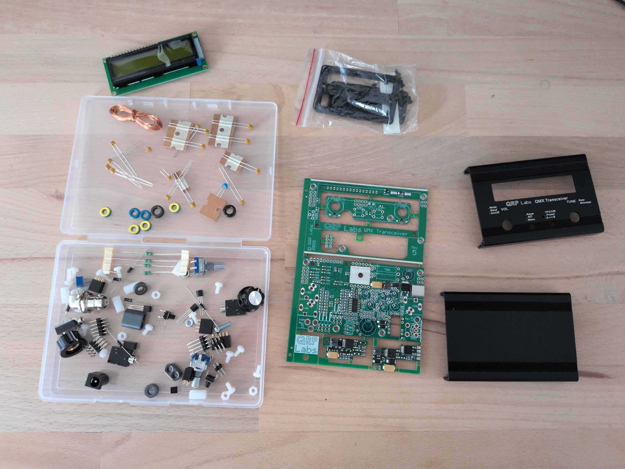
The 10W modification
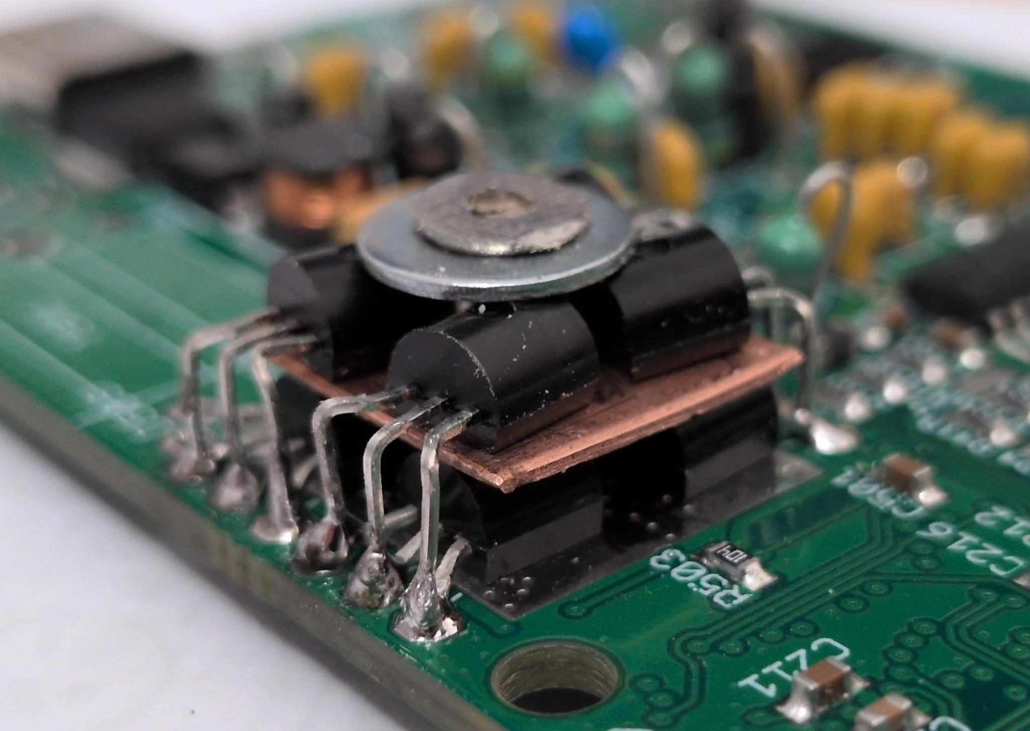
I started by soldering in the four included BS170 transistors. Then I've cut a piece of 0.5mm thin copper sheet and drilled a 3mm hole into the middle of it. After I placed it on the four transistors, another set of four BS170 have been placed on top of the copper sheet and soldered to the underlying transistors. The whole package was then secured by a washer and an M3 screw. To make it fit between the main PCB and the display PCB, I had to make a few adaptions.
At first I filed down the screw's head to an absolute minimum:
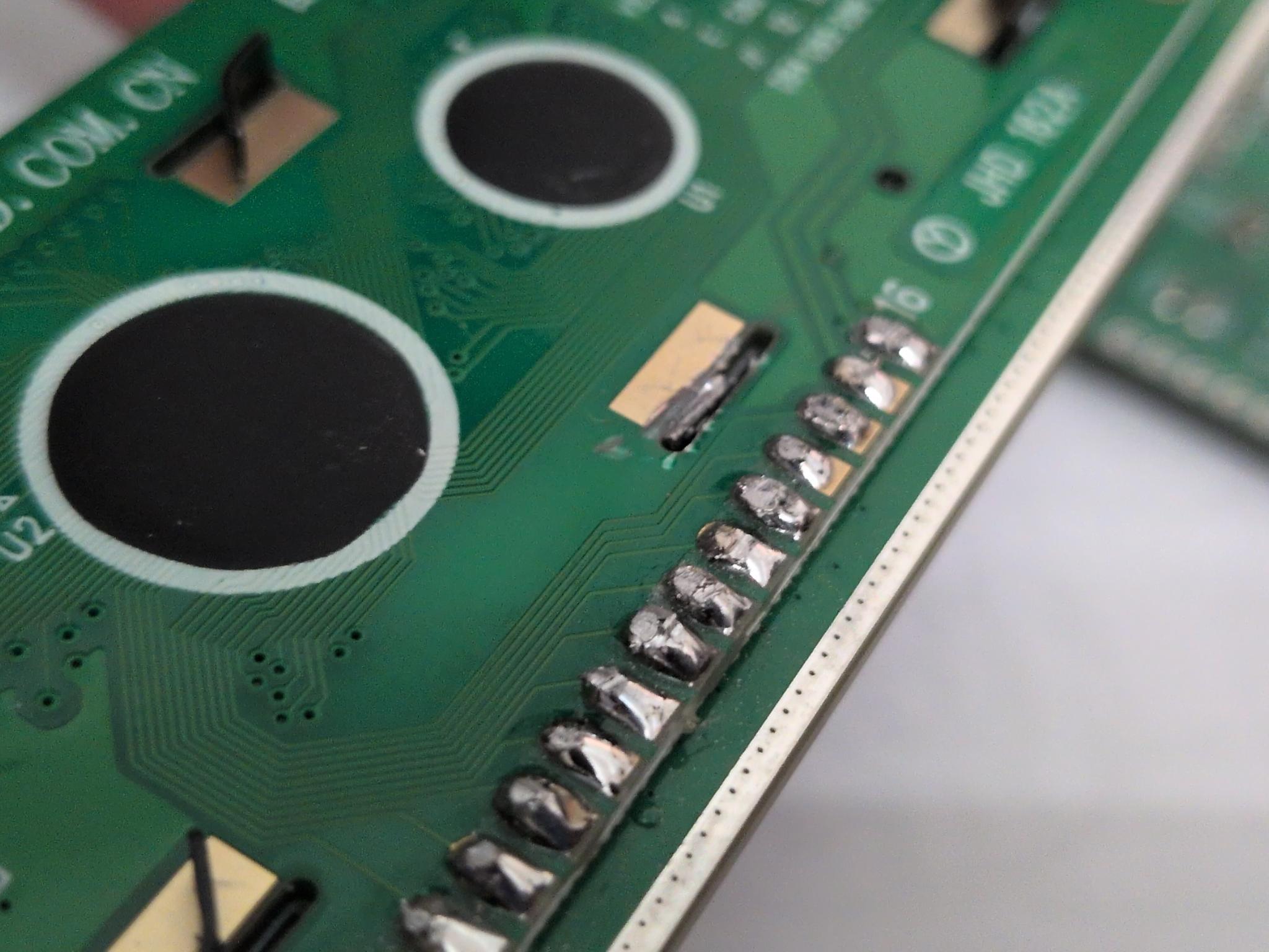
Then I've used a rotary mini tool to grind down one of the six tabs that hold the LCD to the display PCB. I've also grinded down the surrounding solder joints:
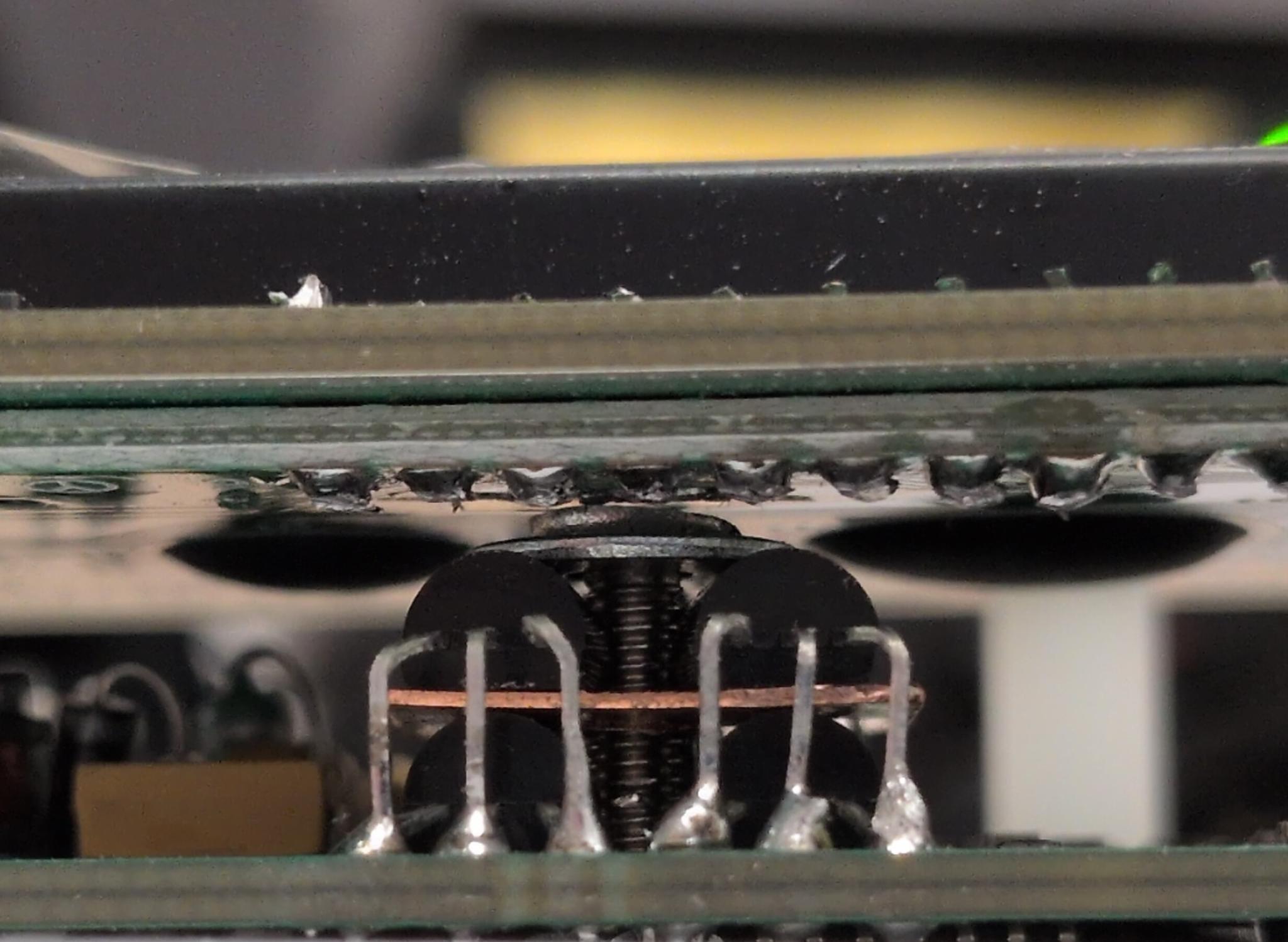
With these small modifications, the eight transistors fit right inbetween the two PCBs:
Building the kit
Building the QMX is a bit more demanding than the QMX+, but the instructions are excellent as usual. I once again chose to build the transceiver for 12V and ended up making a 3:3 WTST instead of the RWTST intended for 12V.
This is what the QMX looked like before mounting it into the enclosure:
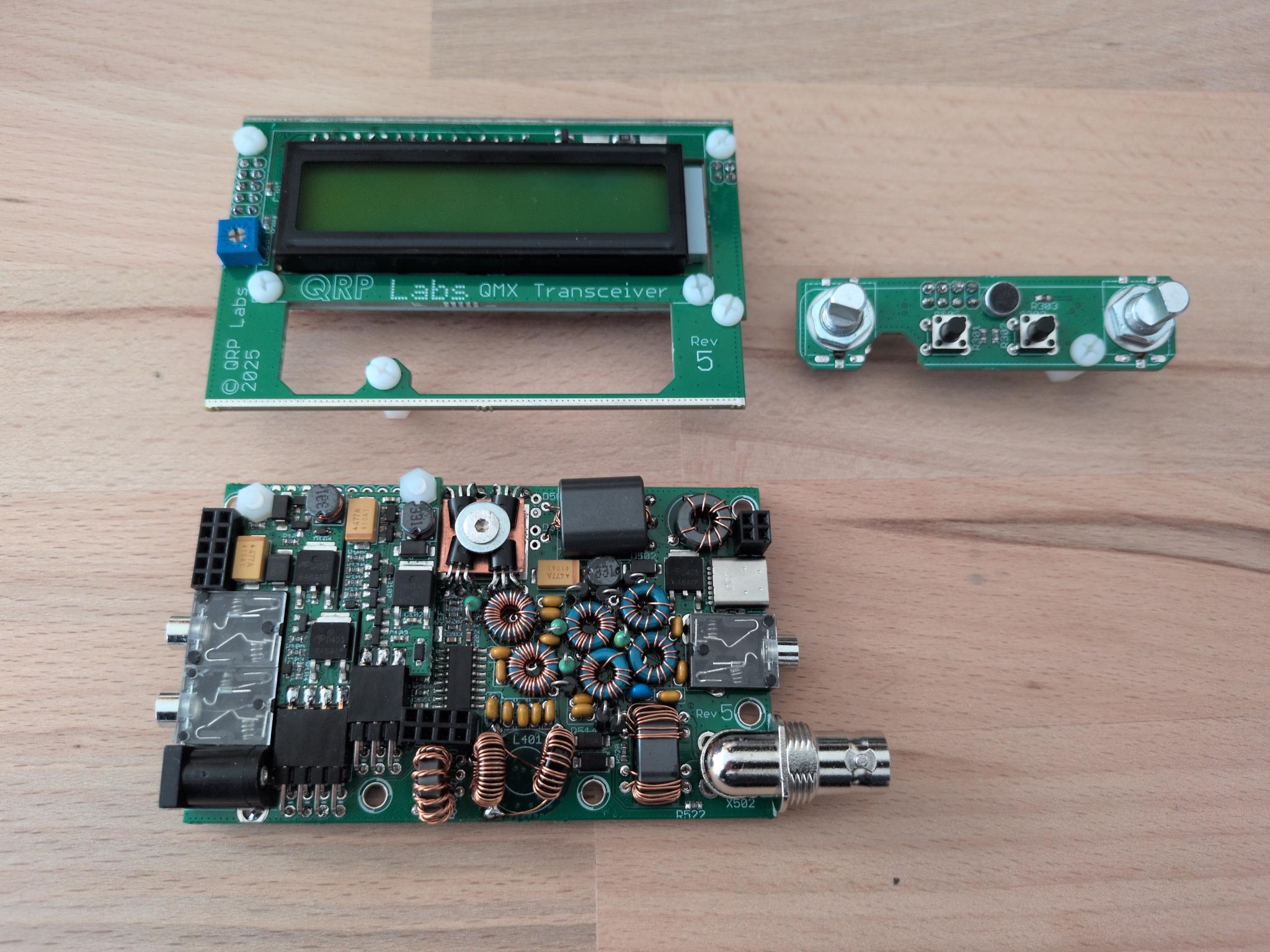
I've later on rearranged the windings on the toroids (see "Issues").
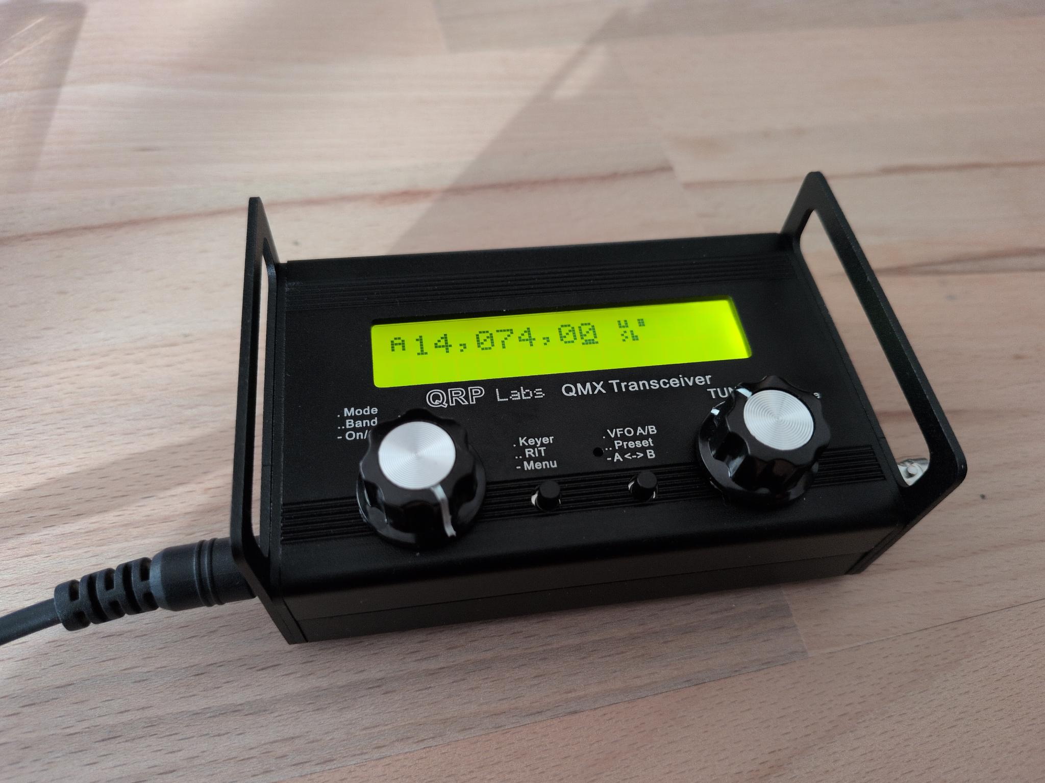
Here's the finished QMX in all its glory:
Issues
I only had some minor issues during the assembly. First, I destroyed a 0603 resistor without realizing it but discovered it during a visual review with the microscope. Replacing it was easier than I thought. Second, I only had an output of 3.5W on 15m while all other bands performed much better. After I have resoldered L510 and L513 and rearranged the windings on the toroids, I measured a satisfying 6.8 W.
Test Results
In the end, all tests went through without any issues. The serial console access to the QMX is brilliant and allows you to test the transceiver thoroughfully. What might be of interest for you is the power output per band that can be taken from the following table:
| Band | Output power | Current | DC input | Efficiency |
|---|---|---|---|---|
| 60m | 10.3 W | 1252 mA | 15.02 W | 68.6 % |
| 40m | 9.7 W | 1216 mA | 14.59 W | 66.5 % |
| 30m | 8.9 W | 1116 mA | 13.39 W | 66.5 % |
| 20m | 11.9 W | 1650 mA | 19.80 W | 60.1 % |
| 17m | 9.7 W | 1495 mA | 17.94 W | 54.1 % |
| 15m | 6.8 W | 1161 mA | 13.93 W | 48.8 % |