
Building the QMX+ as Remote Digital Mode Station
Posted on 2026-04-24Introduction
Over the past few months, things have somehow worked out so that I mainly operate in FM/SSB via satellite and only work digital modes on shortwave. For the latter, I had a Xiegu G90 in my shack, which was connected via about 30 meters of coaxial cable to my 10-meter-long vertical antenna in the garden, right behind the garden shed. It then occurred to me that I could easily work FT8 remotely - with the right setup. To do this, I first set up a test configuration with the two QRP Labs QDX units I already had: one for the lower bands, the other for the higher bands. I connected the antenna to each of the two digimode transceivers via a coaxial relay. All this worked well so I decided to continue the mission.
Since I was in the mood for a new DIY project and like the SWR protection feature in the QMX+ (amongst other things), I ordered one of these kits. I decided not to purchase the original enclosure because, first, I can print my own, and second, I like to have a Powerpole connector for power supply in my devices.
I also decided to build the QMX+ directly with the 10W mod from PA0RDT.
The kit was delivered quickly and consisted of the following parts:
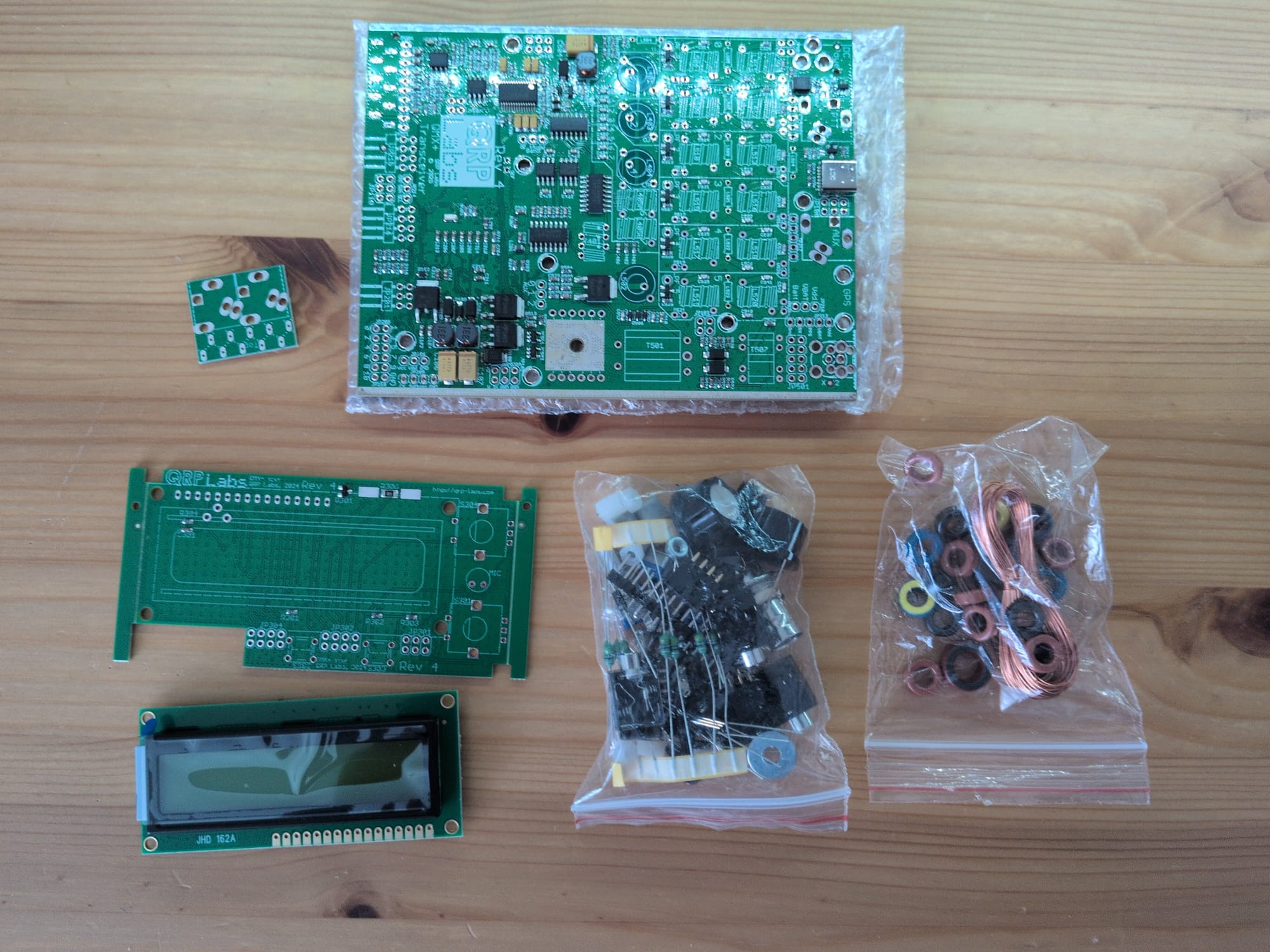
Preparing the 10W modification
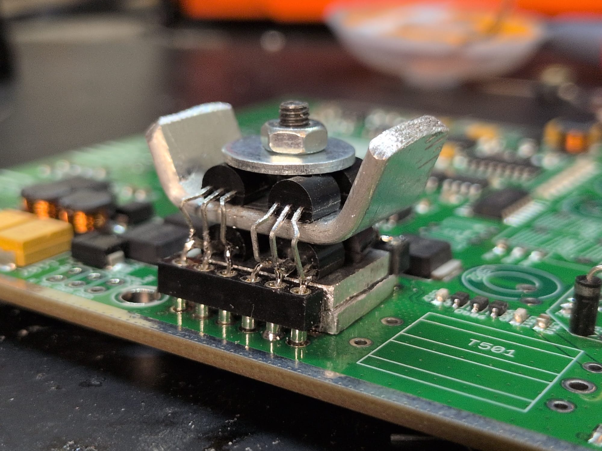
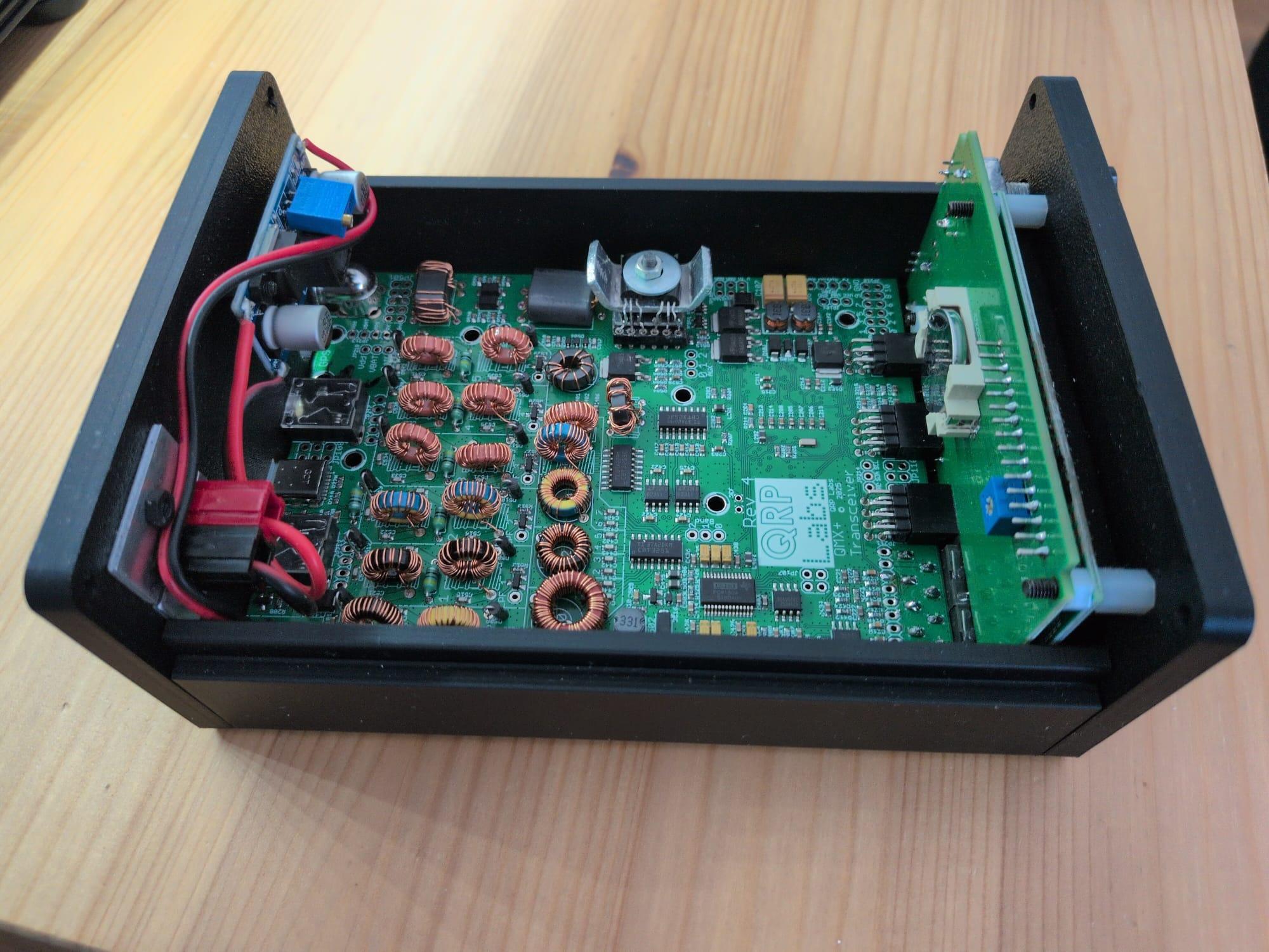
First of all, I took a precision IC socket and cut it apart so that I had two sets of six pins. I soldered these to the main board and then cut two small rectangles out of a 2mm-thick sheet of aluminum; when placed one on top of the other, they fit exactly between the two socket leads and are exactly the same height as them. The idea was to ensure adequate cooling for the lower four BS 170 transistors. I made another sheet, just as wide but longer, for cooling the upper four transistors. I then bent the upper four BS 170s into shape and soldered them together in parallel with the lower ones. The result looks like this:
Building the kit
Building the kit isn't exactly easy, but the instructions are excellent. The only deviation from the instructions was that, even though I chose to build the transceiver for 12V, I ended up making a 3:3 WTST instead of the RWTST intended for 12V.
There were many, many toroids to wind (a few were already soldered into the PCB):
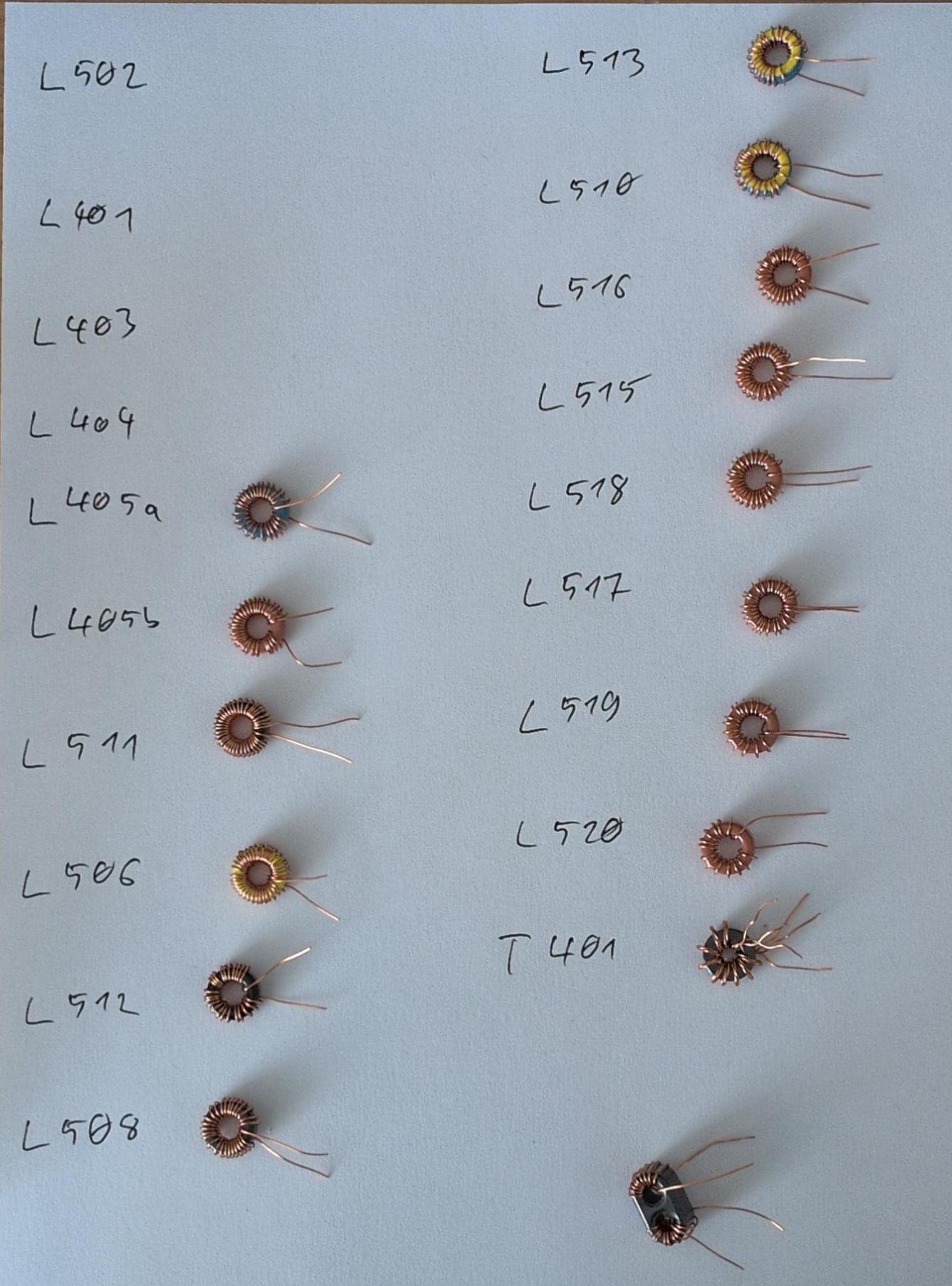
What was much more pleasant this time compared to previous QRP Labs kits is that, instead of 0.6mm enamel-coated wire, they’ve now switched to using wire that’s only 0.33mm thick. Combined with my recently purchased Weller soldering station, I was able to solder the wire in directly and melt away the enamel with the soldering iron without having to scrape it off first.
Printing the enclosure
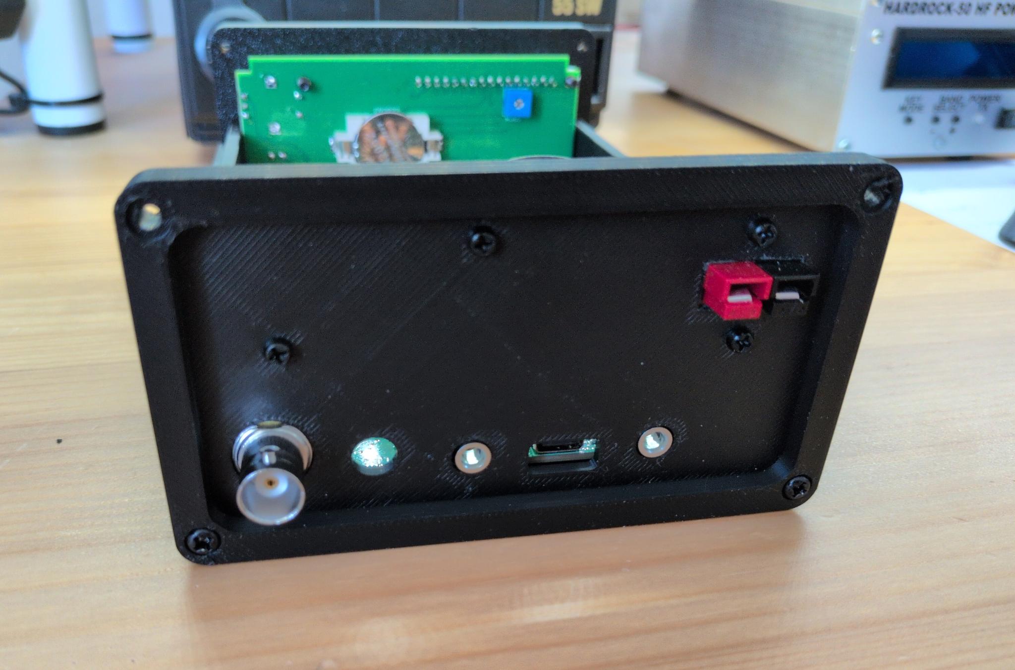
Fortunately, the Printables user 3DSistem has already taken the time to design a printable case for the QMX+. I want all my devices in the shack to have Powerpole connectors, which is why I’ve modified the back panel of this case slightly. First, I removed the hole for the barrel connector and added a cutout for Powerpole connectors instead. I also added two mounting holes for a step-down converter, which can be used to reduce the standard 13.8V voltage in the shack to 12V. My remix can be downloaded here: QRP Labs QMX+ enclosure with Powerpole connector on Printables.com
Final assembly
When installing the circuit boards into the printed enclosure, I was able to follow the official kit instructions exactly as if it were the original enclosure, so there were no surprises. The finished transceiver looks like this: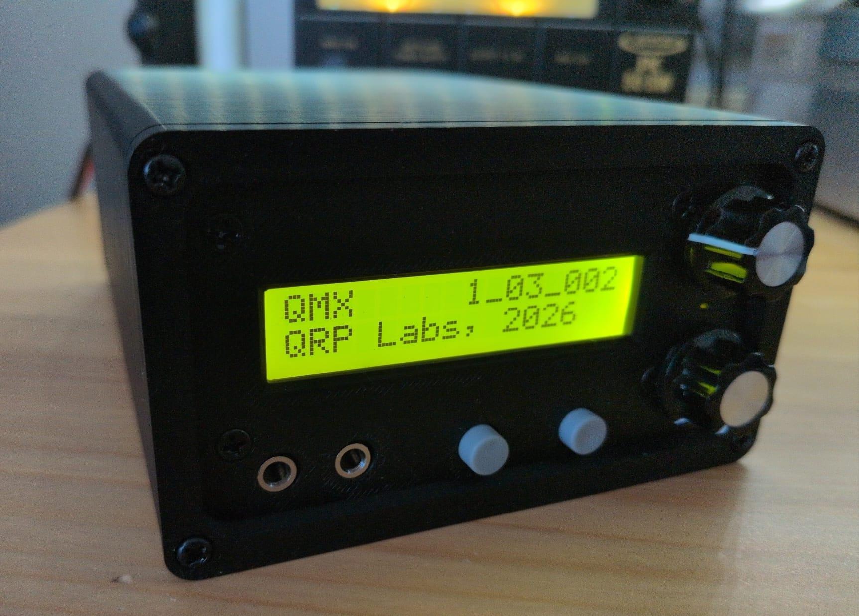
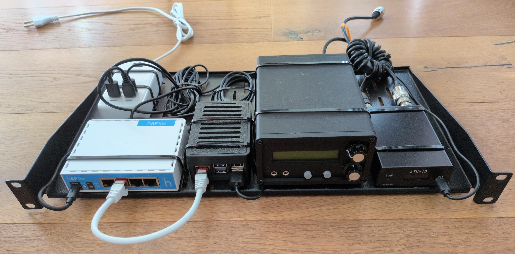
Since the QMX+ is supposed to go in the garden shed, which has a 19" rack, I mounted all the components (switch, Raspberry Pi, QMX+, antenna tuner) on a rack shelf for an initial test setup:
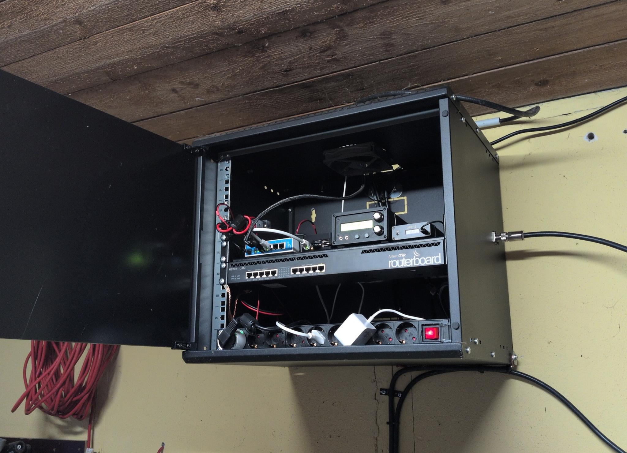
This is what it looks like in the garden house rack:
Testing
First of all, I put the QMX+ into operation using a dummy load and performed various tests using the terminal application, which is accessible via the transceiver’s virtual serial interface: the audio filter sweep, RF filter sweep, image sweep, LPF sweep, and PA amplitude modulator test were all successful on the first try. The measurements of the output power per band were equally satisfactory. These matched Hans G0UPL’s measurements, with the exception that I actually managed to get 10W on 15m.
After that, I made a few test QSOs on the 40-meter and 15-meter bands. These are the bands on which my vertical antenna is resonant. The result was satisfactory despite poor band conditions:
Issues
So far, I've identified two issues that I now need to address:
The QMX+ does not turn on automatically when connected to a power source. You have to push one of the rotary encoders a little longer to turn it on. Since I want to operate the transceiver remotely, I also want to be able to turn it on and off remotely. For this, I have a Tasmota outlet that I can turn on and off via an app. I’m hoping for a firmware update that will allow me to configure the QMX+ so that it turns on automatically.
The other problem is the external antenna tuner. To get it to tune the antenna to the appropriate band, I have to transmit. If I use the “Tune” button in WSJT-X for this, the transceiver transmits at full power. This could damage the PA during the tuning process. Furthermore, I have to disable the QMX+’s otherwise very valuable SWR protection to do this. However, there is the option of switching to the QMX+’s terminal application and transmitting a signal with significantly lower power for tuning from there. However, this would mean that I first have to close WSJT-X to free up the serial port, then connect to the QMX+ via a serial console, navigate through the menus, tune the antenna, exit the terminal application, and finally restart WSJT-X. Not very convenient. For this reason, I’m limiting myself to the 40m and 15m bands for now until I find a solution.
Update 2026-05-02: I've decided to keep things simple and focus entirely on one thing. Therefore, I'm limiting myself to 40m with this station. This also has the advantage that I can run a 40m JS8Call station 24/7. I'll be writing a separate post about this shortly.
Update 2026-05-24: Hans G0UPL, the creator of the QMX+, wrote me the following solutions to the two minor issues mentioned above: Firstly, you mentioned in the part about changing band, needing to shut down WSJT-X in order to free up the serial port for use with a terminal emulator. But for several firmware versions now, there are up to 3 USB Virtual COM serial ports, these are enabled in the System Config menu. Typically two are enough. The third report has been reported to
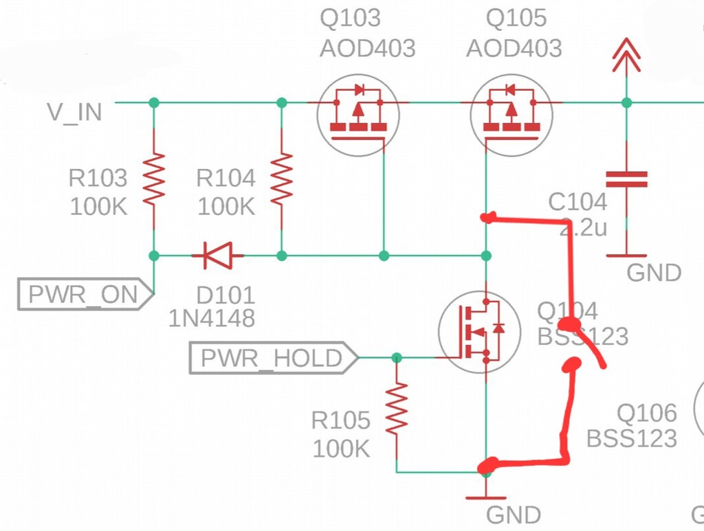
not always work properly on Windows 11. But anyway in your case you're using a Pi so that wouldn't apply, and anyway 2 ports are enough. Worth giving that a try! Secondly you're wishing for a firmware update that would allow remote power-up. That can never happen. The button has to be pressed otherwise the processor won't even be powered up to be able to run any code at all. One solution is to fit a switch as shown in the attachment. When this switch is closed, QMX+ will be permanently on. When
power is applied, it will power up by itself. And you won't be able to switch it off in the normal way either.
Final words
Building the QMX+ was a lot of fun. The assembly instructions are perfect, and the community on groups.io is very helpful. As you can see, it’s pretty easy to make your own minor modifications to the transceiver. The terminal application is fantastic. It lets you test the LPFs and much more with ease, without needing any additional measuring equipment. The configuration options are so detailed that you can, for example, set whether the external PTT should be triggered or not for individual bands.
I’m already able to access the Raspberry Pi in the garden shed rack from anywhere in the world (for example, via VNC on my smartphone) and operate FT8 on 40m and 15m. Now I just need to get the issues listed above under control, and then it will be a solid solution.