Building the CC1200 M17 Hotspot
Posted on 2025-07-17 by DK1MINow that I’ve built the M17 Nokia 3310 replacement board and also modded a Baofeng DM 1701 for M17, it was time to build the CC1200 Raspberry Pi hat. This small device can be plugged on the Raspberry Pi Zero’s GPIO pins and will then act as a M17 hotspot.
Sourcing
This time I also decided to solder myself, but with a hot plate and a stencil instead of hand soldering 0402 SMD parts again. I ordered the components from Mouser, the PCBs and the stencil from JLCPCB. The zip file with the Gerber files and the BOM can be downloaded here at PCBWay. But I have also mirrored them here on my server.
The iBOM, which I created with the help of KiCad, can be viewed here on my server. You might want to click on “F” on the top right as there will be no components placed on the back of the PCB.
Populating the Board
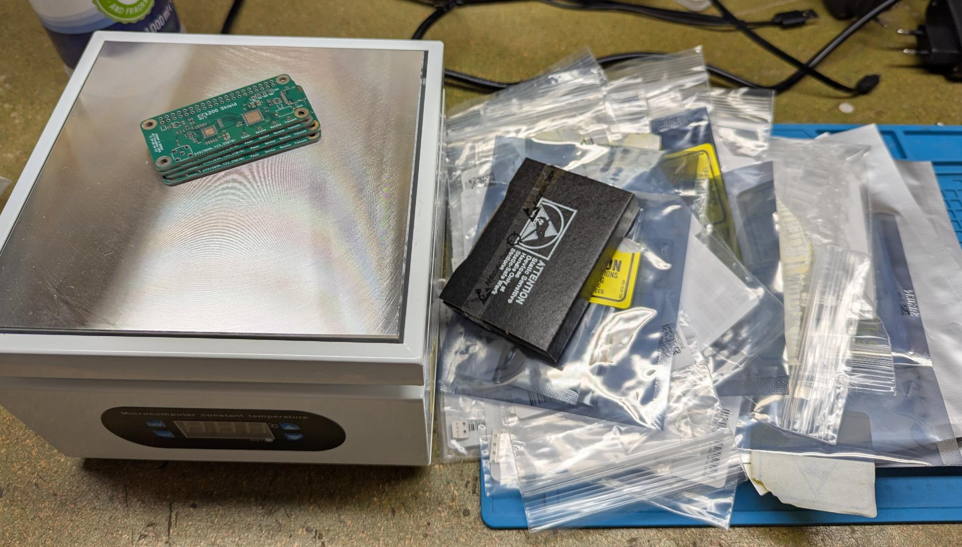
In comparison to the M17 Nokia build, this was a piece of cake - although it was the first time I did reflow soldering. Unfortunately, I didn’t take many photos as it was all new to me and I had to concentrate. First I cleaned one of the circuit boards with IPA, applied the solder stencil and then applied the solder paste with a plastic card. Once I had carefully lifted the stencil off, it was time to populate the board with the components I had previously ordered.
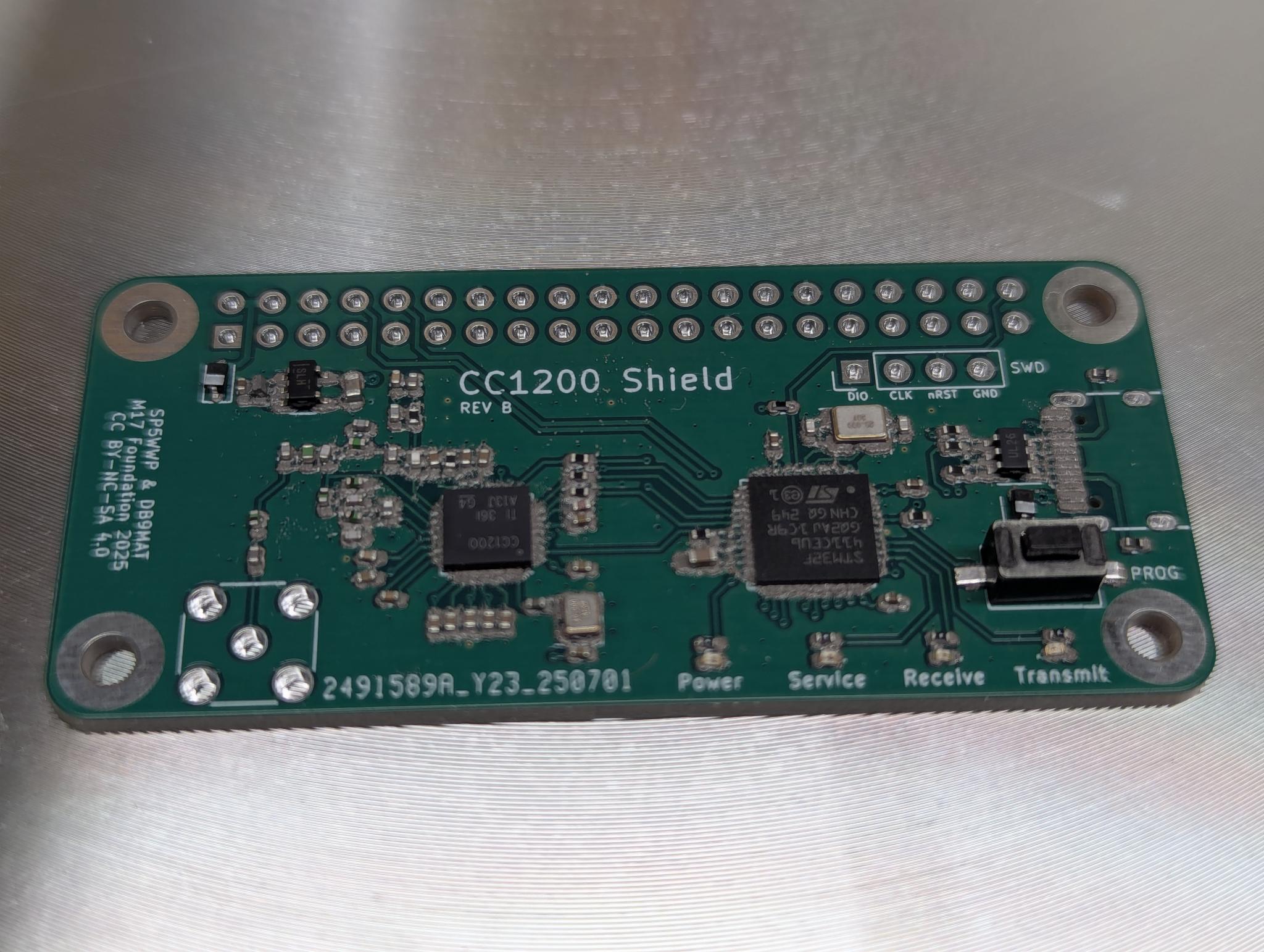
As you can see in the image above, the USB-C port is missing. I somehow messed up the order at Mouser but it turned out that I actually don’t need it. The hat can also be programmed through the GPIO pins of the Raspberry Pi. After spending about three hours of unpacking and placing the components, I placed the board on the hot plate and heated it up. Three or four components were too badly placed, so I had to solder them manually. I then checked every soldering point and re-soldered some of them.
Last but not least, I soldered the GPIO header and the SMA socket.
Setting up the Raspberry Pi
After plugging the just assembled CC1200 board into a Raspberry Pi Zero, I flashed an SD card with the latest version of Raspberry Pi OS Lite.
After the first login, I first updated the OS and then performed the following steps:
- Flashing the STM32 with the CC1200 M17 firmware
- Installation of all required libraries
- Compiling and configuring rpi-interface
I will not repeat the individual installation steps here, as they are described in detail in the M17 Wiki and are also kept up to date there.
UPDATE: There is now a script available, that installs and configures a CC1200 based M17 hotspot for you: Installation Script for the M17 CC1200 Hotspot
Running the Hotspot with rpi-interface
The software rpi-interface is what connects the CC1200 with an M17 reflector of your choice. After you have compiled and installed rpi-interface, you need to copy and adapt the configuration file:
# cp default_cfg.txt my.cfg
Make sure to set your desired frequency, call sign and the M17 reflector you want to connect to. You will need to define the reflector’s name, IP address, the desired module and port (most likely 17000). You can find a list of active M17 reflectors on DVRef.
Here’s an example configuration file:
#Main settings
#log_path="/var/www/html/files/log.txt" #log file for the dashboard
device="/dev/ttyAMA0"                   #UART port to use
speed=460800                            #UART's speed
node="DK1MI H"                         #callsign with a suffix
ipv4="152.70.192.70"                    #reflector's IPv4 address
port=17000                              #reflector's port
reflector="M17-M17"                     #reflector name
module="A"                              #module, single letter
nrst=21                                 #nRST pin
pa_en=18                                #PA enable pin (unused by the CC1200 HAT)
boot0=20                                #BOOT0 pin

#RF settings
tx_freq=433475000                       #Hz
rx_freq=433475000                       #Hz
freq_corr=0                             #frequency correction (integer)
tx_pwr=10.0                             #transmission power, dBm
afc=1                                   #automatic frequency control (0-off, 1-on)
#zmq_port=17017                         #ZMQ PUB port for the baseband signal
One additional, very individual and important configuration item is freq_corr. Tweak this in small steps if your radio and/or cc1200 is off-frequency.
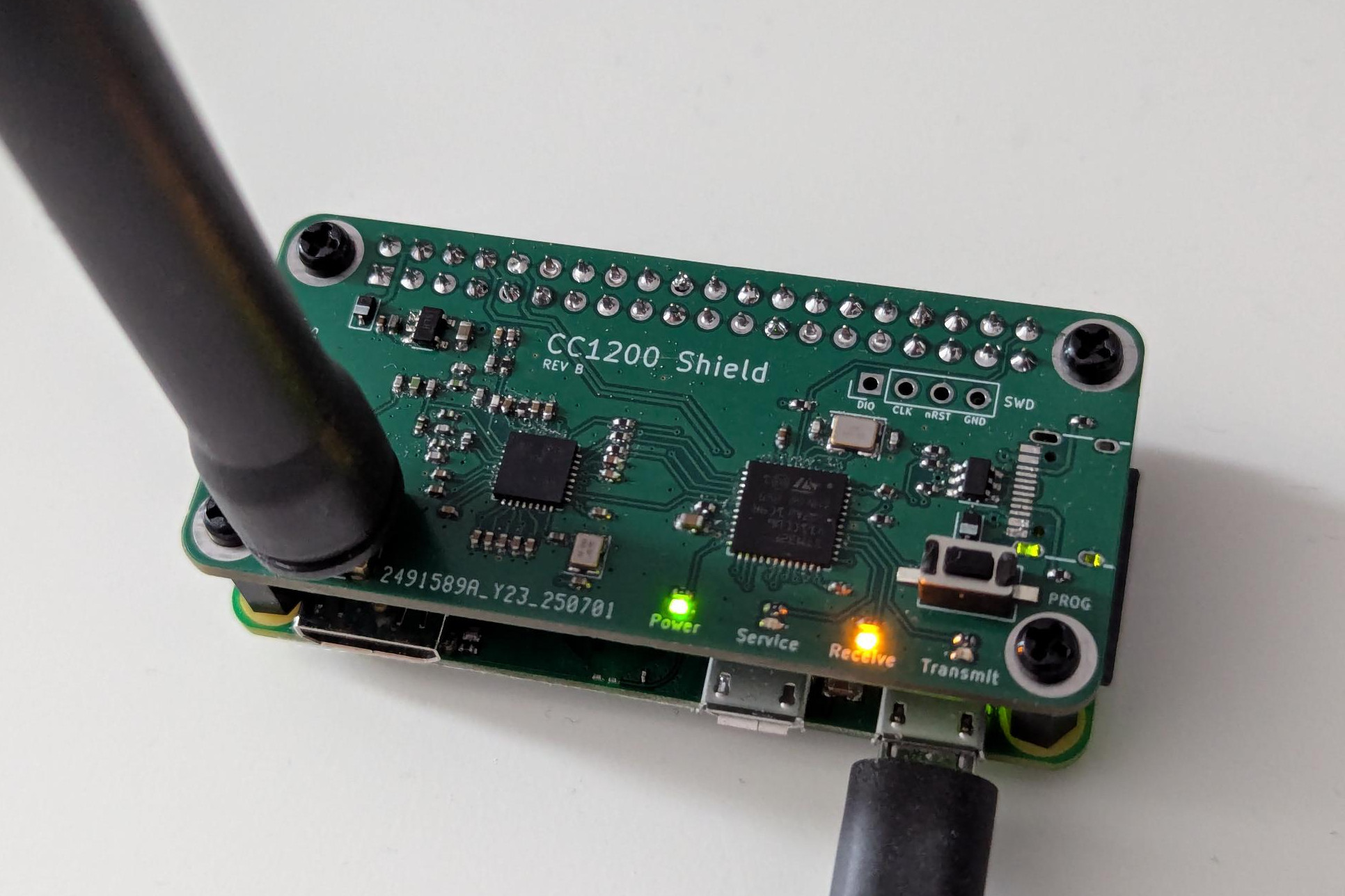
After everything is configured, you can start the application and get on the air:
micha@m17:~/rpi-interface $ ./rpi-interface -c my.cfg
Config: OK
Starting up rpi-interface
Traffic logging disabled
GPIO init... OK
UART init: /dev/ttyAMA0 at 460800... OK
Radio board's reply to PING... PONG OK
RX frequency: 433475000 Hz
TX frequency: 433475000 Hz
Frequency correction: 0
TX power: 10.00 dBm
AFC enabled
Connecting to 152.70.192.70:17000 (M17-M17) module A as "DK1MI H" OK
ZeroMQ disabled
[12:34:12] Device start - RX
Troubleshooting
Surprisingly, the circuit board worked right away. One problem I stumbled upon is that the names of the GPIO pins changed during the Raspberri Pi OS version upgrade from Debian Bullseye to Bookworm. However, this has now been adjusted in the wiki linked above.
If you want to build this or any other M17 project, have questions or problems, I highly recommend to contact the nice people of the M17 Foundation Discord. Without them I would not have been able to get the CC1200 running.