M17 Modification for the Baofeng DM-1701
Posted on 2025-07-06 by DK1MIAfter I’ve finished building the M17 Nokia 3310 replacement board I also wanted to become more active on the M17 voice reflectors. The radio that I have modified already four years ago sadly hasn’t the best audio quality. I’ve recently learned that there is a new radio that is supported by OpenRTX and can be used for M17 which is the Baofeng DM 1701:
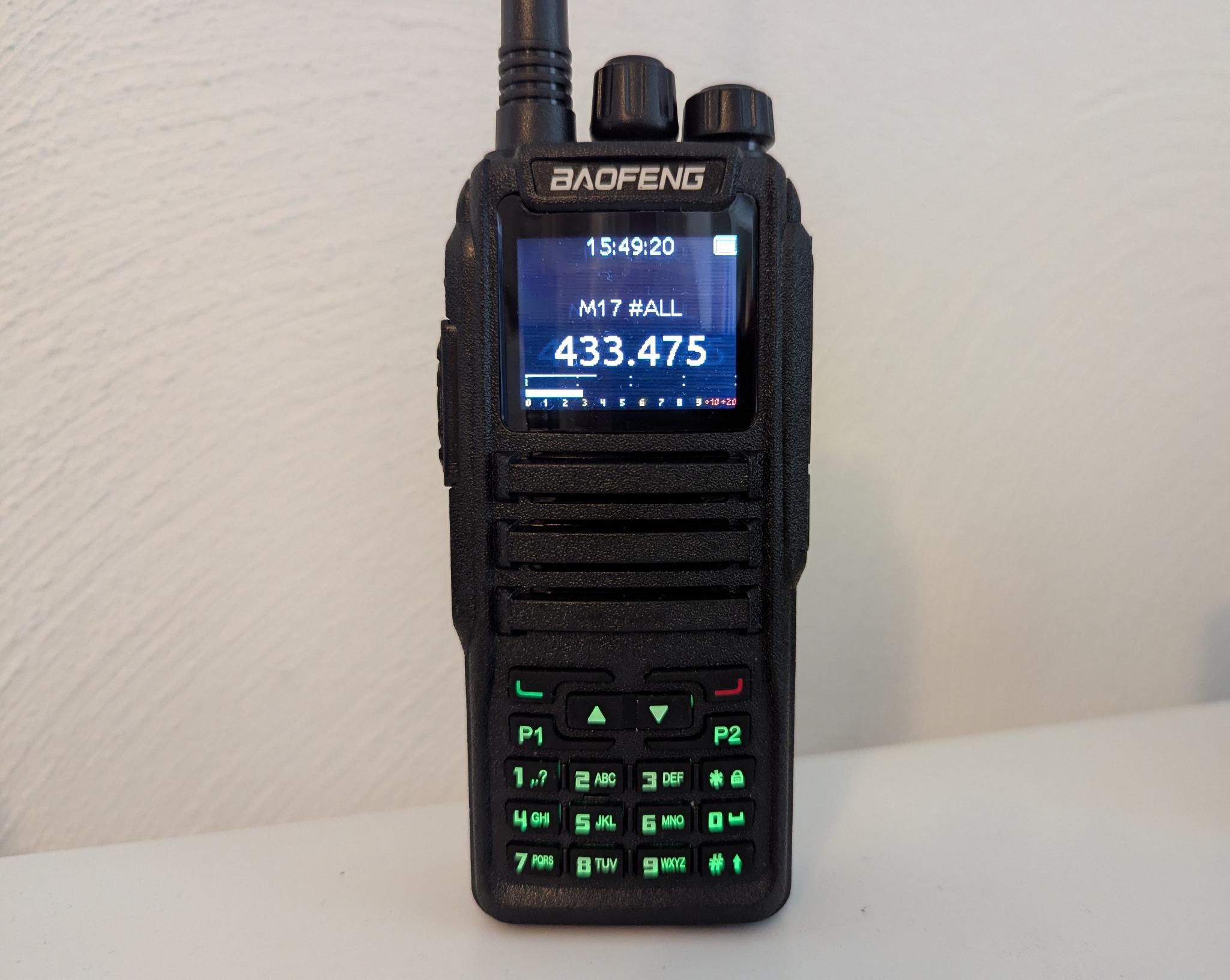
This inexpensive radio needs to be modded before you can transmit in M17. You can find the documention on this mod here on GitHub. In the following I describe how I proceeded with the modification and have a few additions to the original documentation here and there. However, I strongly recommend that you read the manual on GitHub carefully and use it as a basis for your own implementation. I will not repeat certain steps or preconditions here.
Disassembly
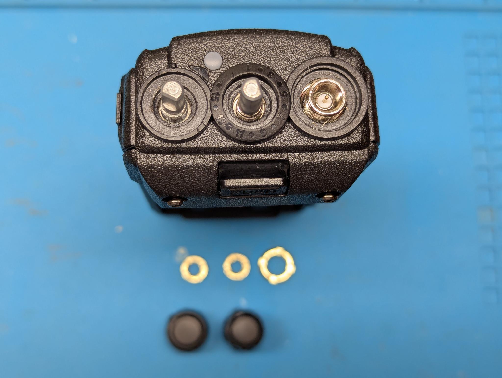
First unscrew the antenna from the radio, then remove the two rotary knobs for volume and channel selection. I used a screwdriver to help with this. The three nuts which then come to light can also be carefully unscrewed with a small flat screwdriver:
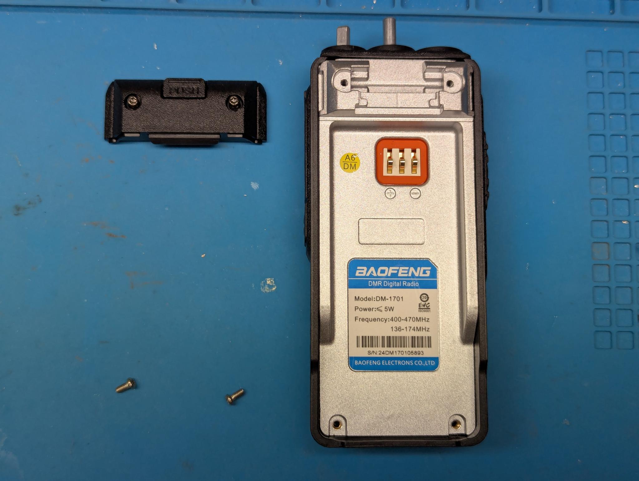
Remove the battery, then remove the top cover (two Torx screws) and the bottom two Torx screws:
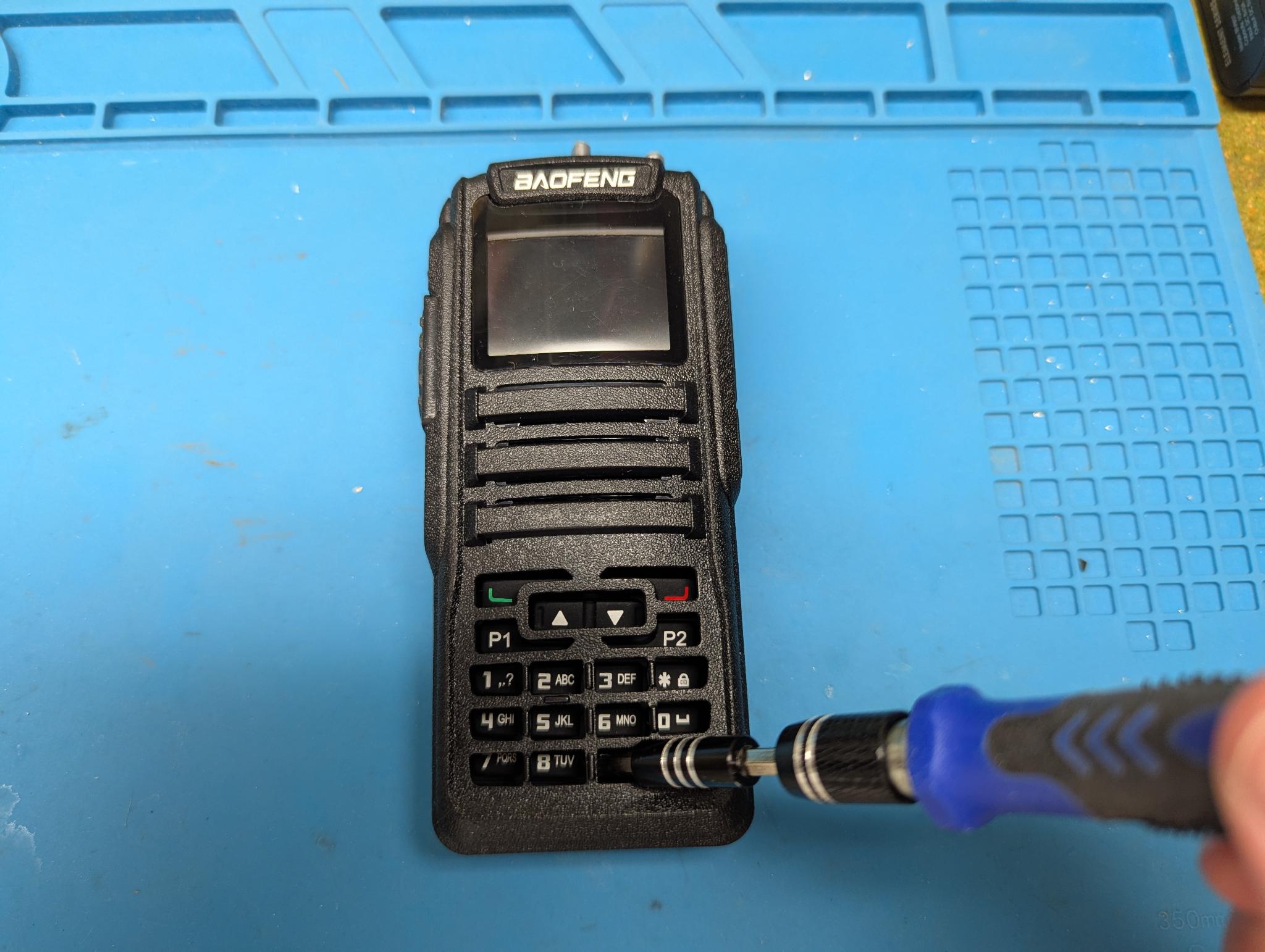
Now the metal inner part can be pulled out of the housing shell. To do this, I simply pressed against one of the lower buttons on the keypad with a screwdriver:
As soon as the inner part is completely out of the lower side, pull it downwards so that the antenna socket and the two shafts on the top slide out of the recesses.
Now carefully place the inner part next to the outer shell without damaging the speaker cables. It is best to mark the two cables and then unsolder them:
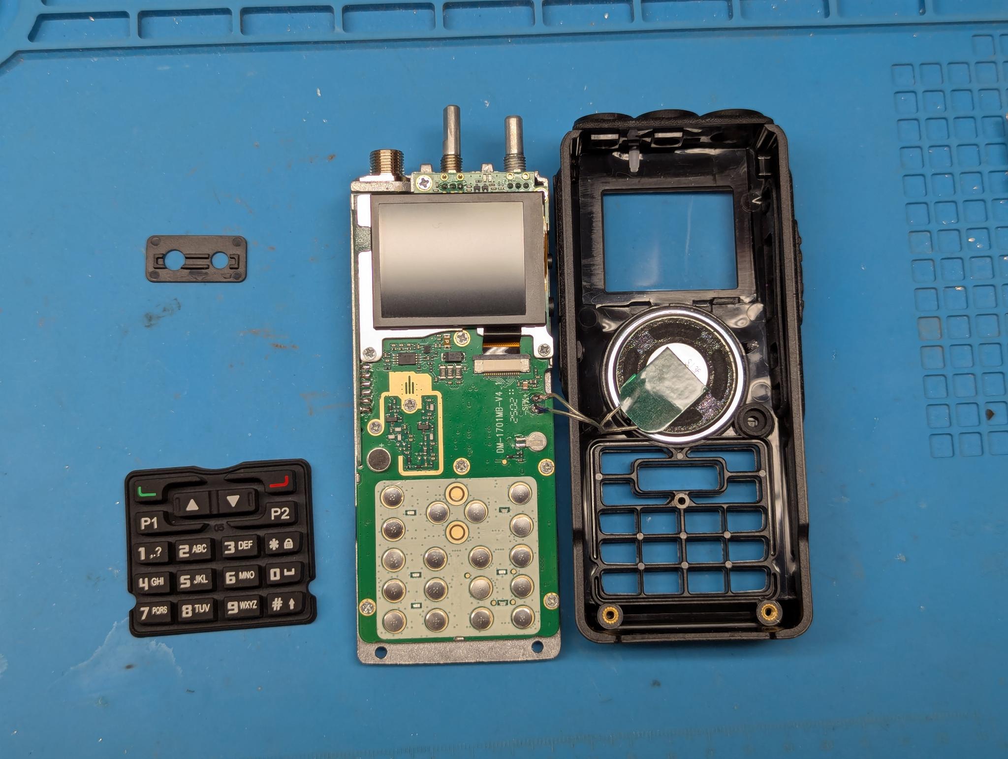
You can use a small flat screwdriver to carefully push the plastic latch upwards to loosen the ribbon cable:
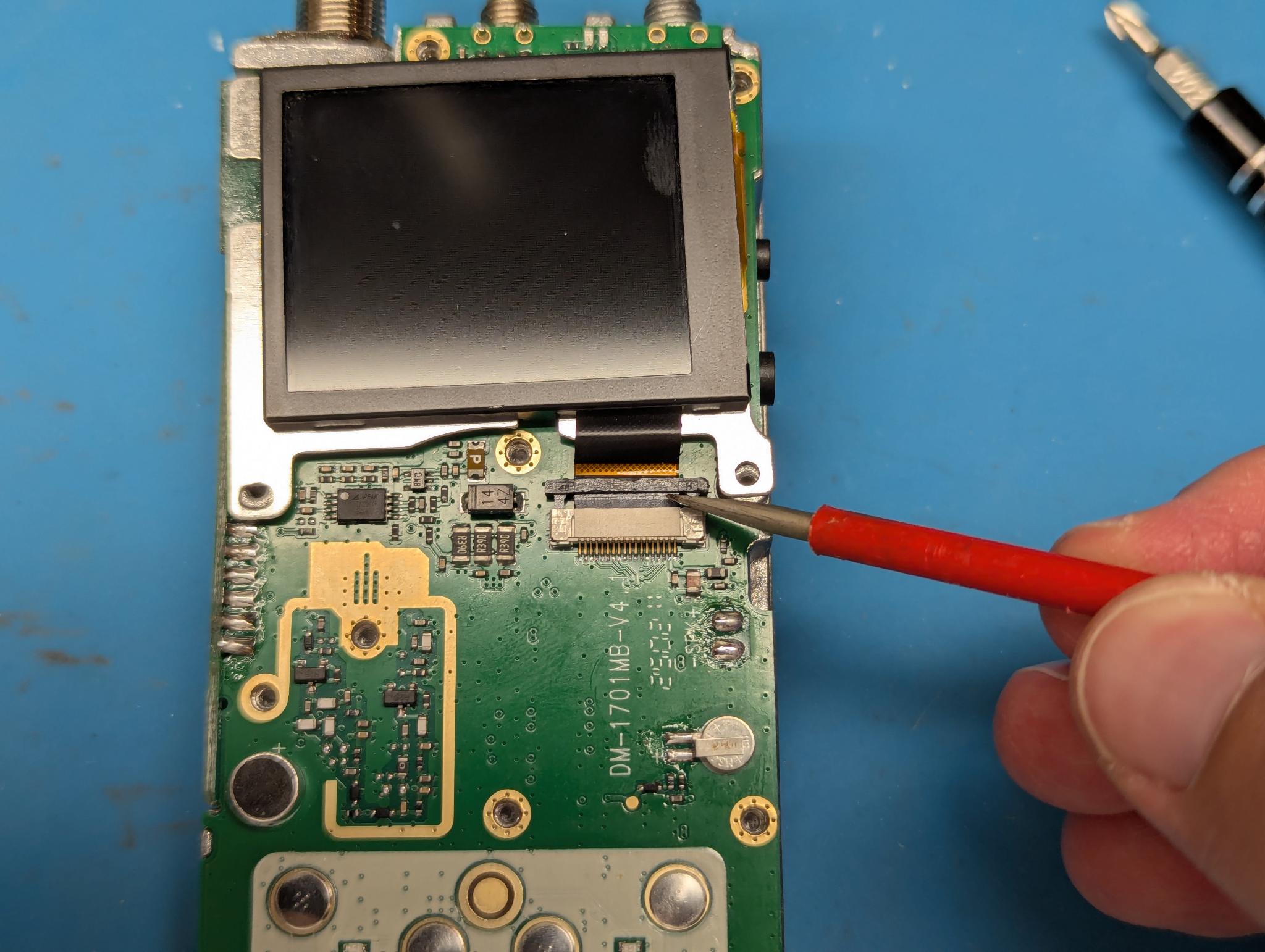
The display itself can now be loosened and removed with two Phillips screws. Then remove all other visible Phillips screws. The last step is to unsolder the antenna socket from the circuit board:
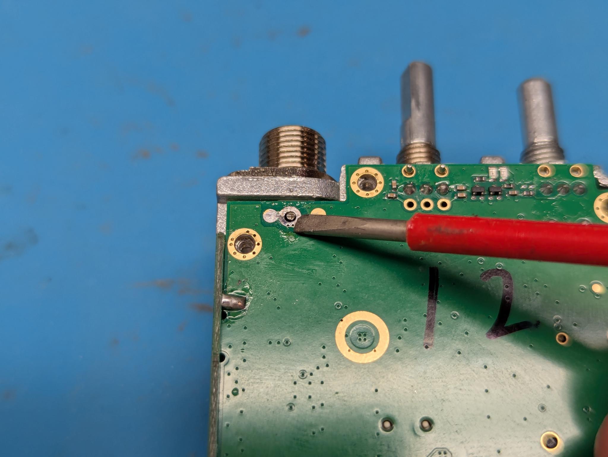
The circuit board can now be carefully removed from the metal inner part.
The Modification
The modification itself can be found on the GitHub page linked above. I’m not necessarily proud of the following pictures, but I’m showing them anyway as they might help. Please ignore the time and date in the pictures. I failed to set these correctly in the microscope and/or to deactivate them.
The Kynar wire, soldered to pin 18 of the MCU:
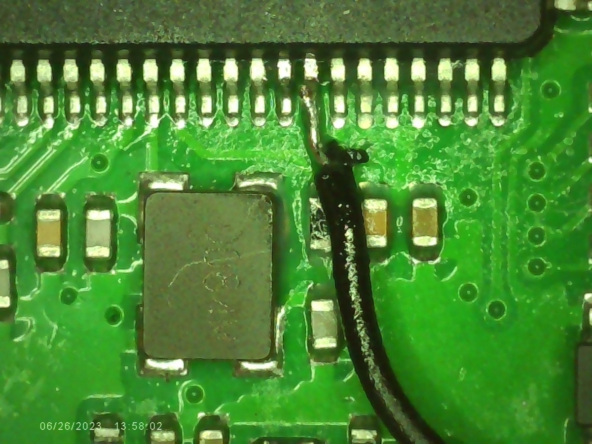
For me it was the best solution to cut the wire to length before soldering it to the PCB. Choose a suitable route, bend the wire before soldering and stick it to the board with some adhesive tape so that both stripped ends are already on the respective pins. Then hold the end with a pair of tweezers and solder with a good amount of flux.
The other end if this wire, soldered to pin 9 of the AT1846:
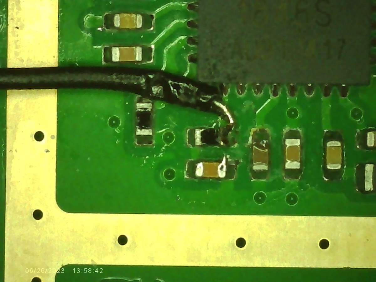
Don’t forget to modify the metal inner part, e.g. with a Dremel, so that the Kynar wire is not crushed.
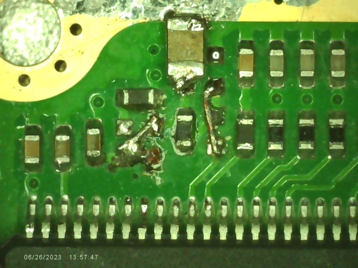
This is the section where you have to desolder some components, add two bridges and then solder a 1.5nF capacitor to GND. I messed up the lower solder pad of the left bridge so I soldered it in diagonally as both lower pads are directly connected:
And finally here the part where you also have to desolder some components and add a 200k resistor as well as a bridge:
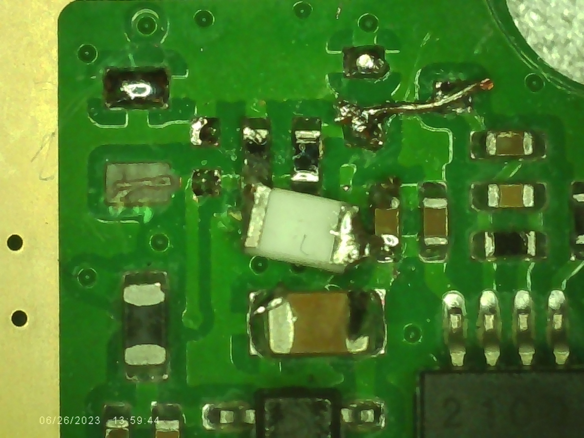
Removing the capacitor close to the HR_C6000 chip shouldn’t be much of an issue.
Reassembly
After all these steps have been carried out, the device must of course be reassembled. To do this, the PCB must be placed back on the housing part in such a way that the inserted wire is not pinched. It can then be tightened again with the Phillips screws. The antenna socket must then be soldered back on and the display has to be mounted with the remaining two Phillips screws. The ribbon cable is pushed back in and the latch pressed down again. Then solder the loudspeaker back on, put the rubber ring on the microphone and push the inner part into the top shell. Do not forget to insert the keypad mat and hold the cover for the Kenwood connector to the side while sliding it back in. Now just screw in the four Torx screws, screw on the three nuts and fit the rotary knobs.
Flashing the Firmware the easy Way
To flash your DM-1701, just
- Power off your radio
- Connect it with the provided cable to your Mac/PC
- Press the upper button on the left side of the radio together with the PTT button while powering it on to put the device in flash mode
- Download the latest firmware from here (direct link to version 0.4.0)
- Open a Chrome/Chromium browser and navigate to https://dmr.tools/#/flashfirmware
- Click on “Connect Radio”
- Click on “Upload from your Computer” and select the previously downloaded file
- Click on “Upgrade Radio”
Your radio should now have OpenRTX flashed. Note: You can do this already before the modification.
Troubleshooting
I had the problem that I could decode M17 transmissions after the modification, but my other radio could not decode my M17 transmissions. I could see that a signal was definitely being received, but squelch did not open and no callsign was shown on the display of the receiving radio.
I had to bug SP5WWP again about this, who then gave me the tip to check the transmissions using SDR++. Here it became clear that the radio was definitely transmitting something that looked like an M17 signal. Unfortunately, I wasn’t very familiar with the software, otherwise I would have been spared a lot of trouble. I disassembled and reassembled the radio a total of five times, resoldered everything and examined it under the microscope.
In the end it turned out that the modification had probably worked right from the start, but my Baofeng was transmitting about 12 KHz too low. After I corrected this using the offset function in the OpenRTX firmware, I was able to make my first M17 QSOs without any problems.
Conclusion
Also this time I learned a lot but what is much more important: I am now finally QRV on M17 with a real radio. The voice quality is good, everything is stable. The only problem with the current firmware version is that all settings including my own callsign, frequency and offset are not persistent - which means that they are gone after switching the radio off and on. This is due to the use of an STM32 clone in the Baofeng, which has certain limitations. However, the OpenRTX team is currently working on another solution to persist settings.
I can recommend the modification to anyone who has the confidence to solder SMD and wants to get on the air on M17 with little money.